Even after being on the second run of prototype PCBs at the last Apple II OzKFest event in Oct 2023 there was still a lot of work to be done in getting this into a consumer product. The OzKFest event was great for getting help with things that otherwise would have been difficult for me to do. Like borrowing a bunch of other video cards to compare against, being able to borrow an NTSC IIe and spending time on a high quality Apple II CRT video monitor for comparing with CRT emulation. I wasn't able to bring these back home with me, so I spent as much time as possible making the best use of the borrowed items. What was clear to me was the fact that I needed NTSC machines to test over a long period (hobby time is sporadic). I also didn't want to be using someone else's pride and joy to be testing my electronic projects (in case I damaged something). Luckily up to this point I've only fried a simple step-down power regulator and two Pi Pico boards which have been cheap and easy to replace. Oh, the joys of working on projects into the early hours of the morning and, hence making simple mistakes. Mainly due to shipping costs, it wasn't a cheap exercise to source two NTSC machines (a IIc and a IIe) but it had to be done. Thanks goes to the "Apple Rescue of Denver" for having the machines that I was after. I organised this to happen over the Christmas vacation so that it did not feel like I had to wait a long time for the machines to arrive.
Due to a new PCB layout and having to fix a few traces (also thanks to late night work) I was then able to use the VSync signal line as opposed to a timer based on the HSync. This fixed most of the NTSC related issues. Then that was PAL, International NTSC and NTSC motherboards covered
I played around with getting the 12V to 5V step down regulator working on the IIc version. I stuck with using the 7805 linear voltage regulator, instead of the switch mode regulators due to the amount of electrical noise on the power rails. Video and sound cards are more susceptible to noise over other cards so the cleaner the power supply the better.
On the subject of generating clean signals, there were many hobby projects that I looked into which involved generating VGA signals using non dedicated hardware ie FPGA / bit banging from a microcontroller. What I found surprising was that I could not find a single project where the developer went through the trouble of designing the DAC (Digital to Analog Converter) to be impedance matched as per the VGA specification. I didn't follow everybody else's lead but instead implemented a better solution. You just never know what quality of equipment the end user is going to have. Once a product is released, hardware issues are very difficult to deal with. You can't test your hardware with every possible outcome so you want the biggest margin of safety that you can get. I do believe this is not only going to result in a better performing product but I'm sure that in the long run it will save me time in dealing with specific support issues.
The last big hardware headache was with a ground loop issue on the IIc. A ground loop is formed from the earth wire going into the IIc power supply, through the ground of the IIc, through the ground of the video card, through the ground of the VGA cable, through the ground of the monitor, through the earth wire and back to ground. If the equipment does not protect against it then it can induce a ripple from the power mains onto the ground plain and cause humming. In this case it results in a high-speed flicker on the monitor. It is barely noticeable if using the IIc normally (varies based on the monitor) however you can make it out when you have a large area of a single colour on the screen that is non-black. I tested this with other video cards and the A2VGA was not the only card with this problem. I don't know how big of an issue this is since I have not been able to find any references to it online. I got my hands on a dozen or so IIc power supplies and about half of them had this problem. I suspect this issue was addressed at some stage and it was resolved in later power supply designs. I was torn as to whether this issue should be fixed on the A2VGA. There are devices such as the "Ground Lift Adapter" which remove the earth wire from your circuit, but I would never recommend these being used. The earth is there for a good reason. It is there to save your life in the event of an unlikely but possible, worse case electrical fault scenario. The option of modifying the IIc power supply was out of the question. Alternately, you could purchase a device such as the "humno" but they are rather expensive. This could be fixed by using some modern reproduction IIc power supplies which don't contain an earth wire, or you could run the signal to your monitor via a "VGA to HDMI converter". None of these sounded like good options to me. As a last resort, I tried to break the ground wire and inserted a very small valued resistor in series. Doing this on the output stage of the A2VGA caused the video to display lots of ghosting however doing this on the input stage of the A2VGA removed the flicker without any noticeable effects. Having the resistor in series on the good power supply did not look to affect the video image either. I added a bypass switch for the resistor just in case. Now you have the option to clean up the high-speed flicker or go with the authentic flicker feel.

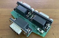
The IIc power supply on the left causes a ground loop issue while the one of the right does not.
The rest of my time was spent on software and administration. There was plenty of work here too. I consolidated the best of the colour models into one package. I worked on adding in the "NTSC-CRT", "Lukazi YIQ" and "DHGR COL140 mixed" colour models. I added Grayscale and Green/Amber monochrome CRT options. I generated the user interface which involved setting up fonts, logos and a "Save to Flash" function. Oh, and I also had to generate a user manual.

Showing the output from the "DHGR COl140 Mixed" colour model.
The Pico IIc and Pico IIe variants had their own individual issues which needed sorting out. However, I didn't want to release one card before the other. That way both cards were able to be updated concurrently and I could keep the same firmware for both variants. Only time will tell if I'm able to keep it that way.
I've attached a link to my PowerPoint presentation from the OzKFest event. https://docs.google.com/open?id=1Q_sV2tWVUSiUlgc5VDFb8NSSEZ1Ohwq5
As a summary, this is how the A2VGA works. There is limited processing power on a microcontroller such as a Pi Pico to perform the maths that is involved in converting a monochrome image into a CRT emulated image on the fly. Hence, we do all the maths externally. The Pi Pico is there just to perform the conversion using a table lookup. This is much faster than doing the maths on every pixel or group of pixels. This lookup table is 4096 entries long (12 bits) and each entry holds the value for 4 coloured pixels (VGA) / 12 coloured pixels (WUXGA). Hence this becomes just a simple streamer. 12 monochrome bits are read from the Apple II which are then used to look up 4 coloured pixels and those 4 pixels are sent to the VGA screen. We read the next 4 monochrome bits, keep the 12 bit window by pushing these 4 onto one side and discarding the 4 bits from the other side. The process then just repeats itself. The trick is deciding on what actual colours the 4 coloured pixels are going to be made up of. Each colour model calculates these 4 coloured pixels differently. There are two approaches in generating this 4096 entry lookup table. One way is to send every possible 12bit monochrome combination through a CRT emulation engine such as "OpenEmulator" or "NTSC-CRT" and then sample the middle 4 pixels. The alternate way is to go through every 4096 entry (programatically of course) and perform some rules. Step 1 is to go through and colour in each monochrome bit that is an "on" bit. You then have have a coloured image with gaps of 1, 2 or 3 pixels in the "off" state that you have to deal with. Step 2 is deciding what colours to allocate to these gaps. The more black you leave in, the more sharp and stripy the image looks while the more you fill in, the more smooth and fuzzy the image looks. In a nutshell, that is it.
The next revision of boards has been manufactured and I'm now just waiting on their delivery. I'll be able to start sending these cards out for testing shortly.