Tuesday, August 22, 2017

CHECKPOINT


CHECKPOINT is based on classic arcade style driving games where you go from point A to point B via checkpoints and do that within certain time restrictions. However, unlike the typical driving game which is computer generated, CHECKPOINT relies on the user driving a real vehicle, not a full-size vehicle although it could be done but a remote-control toy vehicle. The camera feed from within the vehicle results in the game screen showing the driver's perspective as it speeds around the track. The aim of this project was to take the user back to a time of remote control cars, slot cars and train sets, a time when a kid would dream about having a conversation with talking Pontiac Trans Am, time travelling in a Delorian or jumping a police car in orange Dodge Charger.


It was four years ago that I was trawling through ebay looking at Apple II related items. It made my day when I came across a hidden gem lurking amongst hundreds of generic items. The ebay listing was a complete set of items that formed an Apple II based remote-control car controller. Included in the listing was a commercial branded (Heuristics) relay board, software in the form of a cassette tape, a modified hand controller and a LaTrax Alpha RXC remote-control car from 1978. At first, I thought that this was one commercial product due to the Heuristics stickers plastered over the car and hand controller. It didn't take me long to realise that this was actually two different products. This is an amazing set and to me it represents the early days of computer control in the form of a toy project.


Toys are often used to display principles that later become life changing events. Take the Aeolipile (Hero's Engine) for example. It was developed around the year 100 AD and it show cased principles of steam power. It wasn't until the 1500s that steam engines became useful and the 1700s that steam power helped drive the industrial revolution. I found this ebay listing fascinating and I consider it a great example of early computer control with telecommunications. In just a few decades these principals have radically changed the world I live in compared to the world my parents grew up in. I can imagine someone seeing this set operational in the late 70s and wondering what their future had to offer just like I watch science experiments today where super conductors are suspended in mid air and wonder what the future has install for me.

I would have loved to have purchased this great bit of history however the price tag of nearly AU$1000 was a touch above my budget. Realistically I could have purchased it but I just couldn't bring myself to do it. I'm not a museum. I'm a tinkerer and the concept fascinated me more than owning the equipment. What stumped me from the listing was how many pins were being used between the relay card and the hand controller, seven in total. For controlling the car (four controls are required - Forward, Reverse, Left and Right) so I would have guessed that five or eight lines may have been needed but seven? This seemed like a strange number to me. To satisfy my curiosity I contacted the seller and requested more information. The seller provided me with a photo of the underside of the board and gave me some background as to where this set was being used. It turns out this set was being used in a car dealership as a conversation starter. I can just picture the sales person now, saying "Here are the keys to your new car sir. Next time you purchase from us we may have a car that will drive you home." I had a chat to the seller and we discussed how this set could be made functional again. I don't recall if the seller had an Apple II but they certainly didn't have a cassette player.

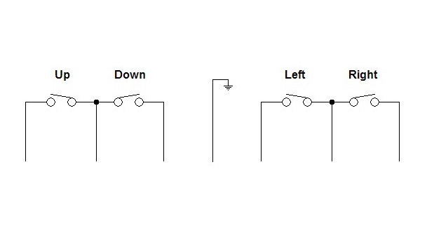
After tracing it out it all made sense.

Now that I had information on the relay card I wanted to see if there was anything special about the software. Obtaining the software from the seller's original cassette tape was not an option. I knew that Brutal Deluxe Software had an archive of Apple II cassette tape images so that was my first point of call. Unfortunately, in this case they didn't have the tape I was seeking. But that didn't stop me from checking the website every few months. About a year and a half later I checked once more and to my surprise there it was. Wow, how often do you get to find something so obscure and rare. I took the wave file and ran it through CiderPress to obtain the program. Reading the program confirmed my suspicions that there was nothing fancy going on. One just needed to poke the first byte of the card's address memory with the byte containing the appropriate bits that corresponded to the four relay switches. The program was written in Basic and was used to select a group of preconfigured movements. These preconfigured movements would then be sent to the relay card which controlled a toy car or robot or anything else that could be controlled with a few switches. Even though I didn't find anything useful in the program I found the programming style very interesting. This was early days of home computing and the style very much represented that.

Stuck with this information I wanted to reproduce something similar to this set. What I needed was to get my hands on a remote-control car. I could have popped down to the local shops and picked up a generic remote-control car however interfacing to it may have been a problem and it just would not have been inspiring enough. I decided to track down something more attune to my childhood. I had other projects to work on so it took a year or so before I found something that was affordable and would suit my purposes. The purchase was for two Hitari built remote-control cars (KITT and the General Lee). I figured that this would give me plenty of spare parts, the electronics would be through hole and easy to work with and if I could work out a way of changing the frequency on one of the cars then I could incorporate both cars into the project.


While waiting for the cars to arrive I built and tested the relay card. This relay card is based on the Heuristics one but contains eight switches instead of four and can be easily configured for different connection scenarios (to my LEGO robots). The cars arrived and I configured one of the hand controllers to the relay board. These cars have digital control circuitry (compared to the LaTrax Alpha RCX which has analog) so the wiring to the relay board is different. The Hitari cars also have six controls instead of four. The extra two are for the horn and the second forward fast speed. A simple basic program was written to take the Apple II joystick movements and use them to control the remote-control car. All this went smoothly and to plan.


Playing with the Apple II and the toy car was good for about five minutes. After that other pastimes looked more interesting. This may have been a spectacle in 1978 but in 2017 it's old hat. I had to find a way of making this more interesting and since OzKFest was only a few months away I wanted something to present that wasn't going to be outdone by the likes of Jason and his LEGO Cannon. Jason's LEGO Cannon is an Apple II controlled firing device constructed from the Boulder Blaster 70747 Ninjago LEGO set and using the LEGO TC Logo parts for movement control. A pinhole camera is used for targeting. Jason presented this at the last OzKFest event.

I decided the best way forward was to make a game out of it. Hence CHECKPOINT was born.

The first enhancement step was to add a video feed to the car. This was done by purchasing a miniature camera and a composite transmitter receiver pair. I could have gone with the more expensive hobby quality stuff but to limit the weight and power supply options the toy class parts seemed more suitable. This worked great after being wired up. So I thought. There was an angry mob outside my door when the household realised that it was me who had been disrupting the home WiFi network with my project. Things settled down after I located the manual online and found I was able to shift the transmission frequency outside of the home's WiFi range.


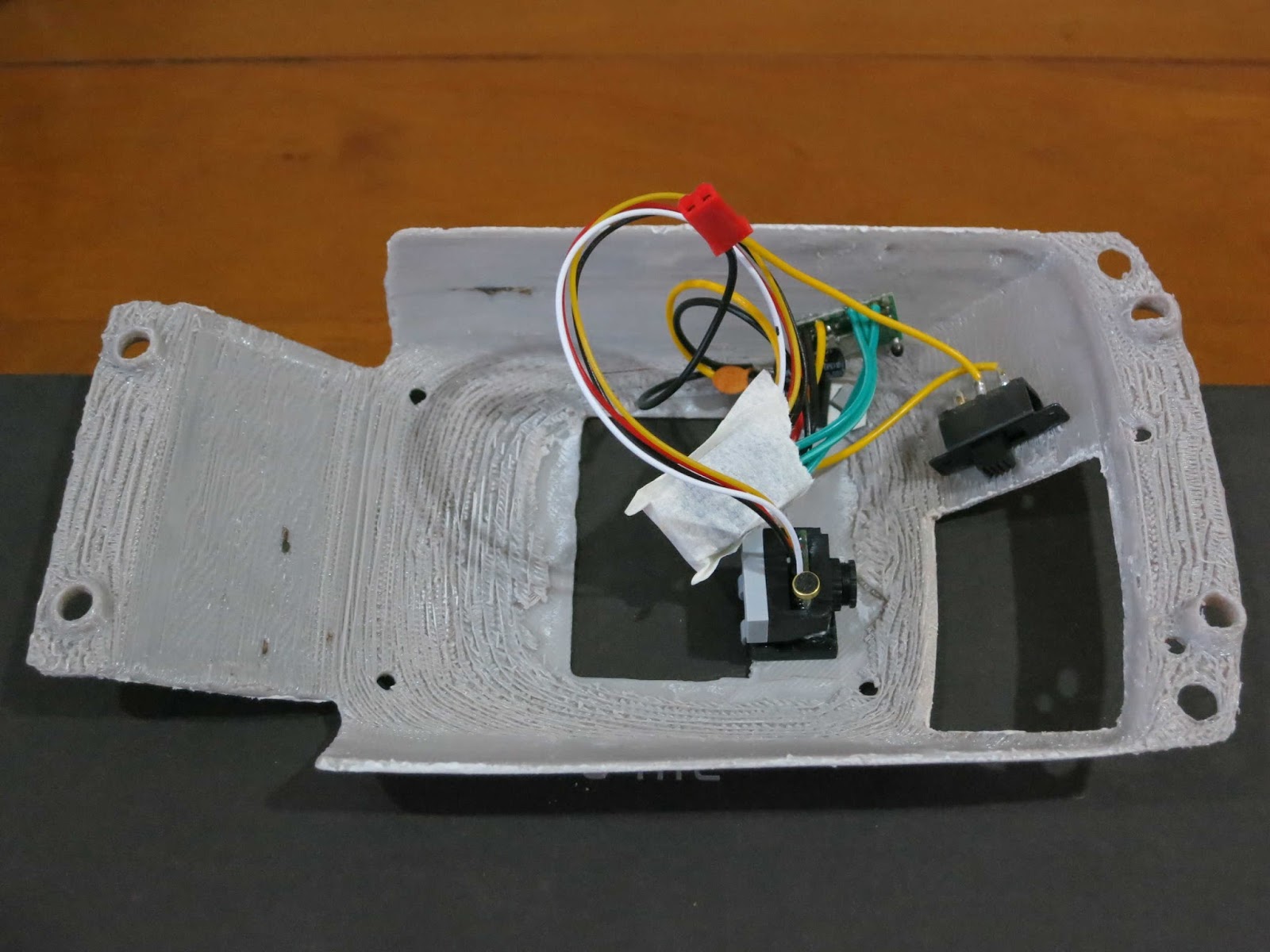
I decided to mount the camera and transmitter inside the remote-control car but in a way without damaging the vehicle. I took it apart and removed the internal shell which made up the windows and roof support structure. By scanning the shell and 3D printing it I could make the required modifications and have the option of returning the car back to its original state if needed. I borrowed a friend's Makerbot Scanner but due to the complexity of the car's shell the 3D models it produced were less than optimal. I found that taking fifty odd photos of the shell and running them through Autodesk's ReMake software produced better results. I went through a few iterations of this before I was happy with the outcome. Only a small amount of editing was then required on the 3D model to smooth it out. Dean helped me with the 3D printing and we got the scale right on the second print. A work college helped me out with the painting options.

To display video from a wireless camera the setup only requires a composite monitor. However, because I wanted to mix the video signals and the computer generated text in the form of a game I needed to incorporate a genlock card. It so happens that I had a genlock card (the Apple Video Overlay Card) just lying around waiting to be used. I had been wondering what to do with this great under-utilised card and now I've found a great use for it. I played around with some timer code in Basic and displayed it as a countdown clock on the screen while having the video feed playing in the background.


Having the timer was great but there was no way of determining when the car had reached its destination. I didn't have anything that would inform the computer of the car's position. I had a few Usborne books from the 80s that showed me how sensors could be wired from slot car sets or train sets or robots to relay back the information to the computer. However, I didn't want to go about running wires everywhere. These days we have plenty of wireless solutions like Bluetooth, RF, ZigBee, WiFi just to name a few. I've had my eye on the ESP8266 WiFi modules and so I figured I could use these for the project and be able to play around with them at the same time. I ordered a handful of them. The cheaper modules I setup as clients since all they need to do is receive a digital signal from a sensor and pass that information onto the server module. I experimented with various sensors (switches, infra-red modules) that would trigger from a passing car. I had issues with using the cheap infra-red sensors during the day time due to the amount of sunlight in the room and their sensing distance wasn't as far reaching as I had hoped. More work needs to be done in this area to get a better solution. The more expensive WIFI module (NodeMCU) brings out many Input/Output pins so it serves as the server which receives the digital location signals and passes them onto the computer via an input card. I used the 4play card for this because I had one on hand and it was easier to setup and use than my other input cards.

The beauty of using the 4play card is that I could now change over from using an analog joystick to using a digital one. The digital joystick is a perfect fit for this type of situation because it matches the four position digital control of the car very closely. The speed difference between processing a digital joystick vs processing an analog one is quite large especially when it's being done in Applesoft Basic.


The last peripheral card that I used for the game was another under-utilised card called the A2MP3 card. It allows you to play, stop and pause mp3s under computer control. Since I'm no musician and to add music to CHECKPOINT would have taken me a considerable amount of time, it was easier for me to sample the theme music and play it back during the game. Since this game is a very customised solution I didn't mind using the A2MP3 card for the game sounds and background music. Using the A2MP3 card was not a trivial procedure. The problem was that I didn't have an A2MP3 card and Vince no longer sells them. I could have borrowed one but there was another option. I had the PCB of the A2MP3 card which I used for my serial Bluetooth concept a few years back. I was missing the part that does the USB file reading and the sound generation but the good thing is that these are still available from electronic stores. The original A2MP3 card came with the FTDI's VMUSIC2 module but I purchased the VMUSIC3 because I already had a firmware programmer for it and it was meant to be plug in replaceable. Plug in replaceable it was not. This was due to Vince using improved firmware in the VMUSIC2 module. I had two options. I could rewrite the firmware for the VMUSIC3 module or I could change the A2MP3 software and do a modification to the A2MP3 base card. I chose the second option since it was the quickest solution and I was quickly running out of time.


I put together the game code, double hi-res title screen, a few theme related props and the OzKFest Powerpoint presentation. This only left me with just one day of system testing. On this day I found out that the noise (electromagnetic interference) generated by the car's motors was enough to cause the video feed to drop out. After giving the video camera and the transmitter its own power source I found that the drop outs had reduced but had not been eliminated completely. This is a classic engineering problem however it's a shame I didn't have enough time to get this sorted before the OzKFest event. There are still many improvements to be done however at least now I can work on them at a less stressful pace.

Thank-you to everyone who helped out with the project. Thank you to the tool builders who make my life easier and thank you to those that take the time to archive and preserve our retro artrfacts. Without these efforts, I would not have been able to do what I do and be able to experience these great extensions of my childhood past. This project is a great example where things are only possible because I have been able to stand on the shoulders of giants. Cheers.

Code and video to follow (one day).

Monday, August 21, 2017

Apple II 4play Joystick Card - Software Resource


I recently noticed that the software which supports the 4play card is scattered about in various locations. I have also been contacted by a few members of the Apple II enthusiast community who have graciously sent me their software conversions. I figured that this might be a good time to consolidate the information. The result of which is the following table. I'll add more software to this list as it becomes available.

Some games are better played when using paddles, some games are better played using an analog joystick and some games are better when played using a digital joystick. It's not my intention to convert every Apple II game to be 4play compliant, just the ones that are easy to convert (the ones that are already digital enabled ie Atari Joyport ones), multiplayer ones because the Apple II was always lacking in this area and also the ones that are the reason why a lot of us got into computing in the first place ie to reproduce that arcade experience at home and not have to spend one's entire pocket money on arcades at the local milk bar. Although I must admit that these days MAME does a great job of fulfilling that need.

Program(s) 4play adaptation/conversion by Apple II card slot Driver 4play port usage Comment Links
KABOOM! Jesse Blue Any Integrated 1, 2, 3 & 4 http://www.ninjaforce.com/html/products_kaboom.html
Star Blazer,
SuperPuckman,
Pac-Man (Atari version)
Lukazi 4 Replaces keyboard code 1 https://docs.google.com/file/d/0B5PVarmqxaOnUUN6OVIteWFqalk
Lode Runner Brutal Deluxe Software Any Replaces joystick code 1 Second web link is for conversion notes and discussion with Antoine. http://www.brutaldeluxe.fr/sourcecode/4play.html
https://docs.google.com/open?id=0B5PVarmqxaOnVXd2OEVtcTl4Q0E
Tapper Michael Sternberg 4 Replaces keyboard code 1 https://docs.google.com/open?id=0B5PVarmqxaOnR00tNXNuM3VFaU0
Boulder Dash,
Boulder Dash II,
Seadragon,
Spy's Demise,
Wavy Navy
Lukazi 4 Replaces "Atari Joyport" code 1 https://docs.google.com/open?id=1U2ZaPhB8TDHceTgKS-jVUeXZNNv4KEq7
Robotron 2084 Nick Westgate Any Integrated 1 & 2 Play as per the original game design ie one joystick for movement and one joystick for shooting. Also supports two analog joysticks. https://drive.google.com/open?id=0B3JBd-TShLlLbldncTJmcHh2NWM
CHECKPOINT Lukazi 4 Integrated 1 & 2 Maybe one day.
Alien Typhoon,
Atarisoft Galaxian,
Starcraft Galaxian
Lukazi 4 Replaces joystick code 1 By popular demand. https://docs.google.com/open?id=1dmvALkPWyiJsb1paglW2eRNIFINMY-VB
Buzzard Bait,
Dino Eggs,
Miner 2049er,
Miner 2049er II,
Plasmania,
Stellar 7
Lukazi 4 Replaces "Atari Joyport" code 1 Some more easy "Atari Joyport" conversions. https://docs.google.com/open?id=1U2ZaPhB8TDHceTgKS-jVUeXZNNv4KEq7
Mario Bros Lukazi 4 Replaces joystick and keyboard code 1 & 2 Two player co-op. https://docs.google.com/open?id=1rsAtvUEg51EA9Y9YQ4mJhPVKqixR-7Gs
Super Taxman 2,
Vindicator
Lukazi 4 Replaces H.A.L. Labs Gizmo code 1 https://docs.google.com/open?id=1ub-yC-yqrjAOmS8MhEK9v5LmkMrSC8Xo

Sunday, June 4, 2017

Bluetooth Game Port Receiver


A few months ago 8Bitdo released an Apple II coloured version of their PRO GamePad Bluetooth controller along with a receiver that can replace the need for an actual Apple II joystick https://www.kickstarter.com/projects/8bitdo/ap40-a-bluetooth-controller-for-ios-android-mac-pc. I love their controller but the receiver was initially implemented without the full analog range which is required by many Apple II games. I believe they have now released a firmware patch which addresses this issue but it makes me sceptical. Is the receiver's hardware design as polished as the product presentation and packaging? I started building my device without knowing if 8Bitdo were going to fix their receiver. This project was never an attempt to make a competing product but to use this as a stepping stone to build bigger and better things. That's the beauty of being able to make something yourself, you can customise it to do whatever you like.

There is no mystery as to how to hook up a wireless controller to the Apple II. It's just a simple extension of RetroConnector's "USB JOYSTICK INTERFACE FOR APPLE II" product (http://retroconnector.com/products/apple-ii/usb-joystick-interface-for-apple-ii/) which has been out for years. Add a USB Bluetooth Host dongle, a HID game controller and a bit of extra code and you're done. If you wanted to stick with the AVR/Arduino theme then the Bluetooth code can be located at https://github.com/felis/USB_Host_Shield_2.0 and the write ups can be found on https://www.circuitsathome.com/mcu/ps3-and-wiimote-game-controllers-on-the-arduino-host-shield-part-3/ and http://blog.tkjelectronics.dk/2013/12/bluetooth-hid-devices-now-supported-by-the-usb-host-library/. Alternately there are several other embedded USB hosts around which could be used. For example http://www.hobbytronics.co.uk/ps4-controller-bluetooth do a pic based one.

I wanted to build a Bluetooth receiver myself because the task did not look all that difficult, I would have full control of how it would work and because I was looking at playing around with a USB host for another project anyway. Initially I looked at using a single Bluetooth module to do the Bluetooth part and the Apple II game port signal processing all in the one chip but it looked like quite a bit of work since most chip manufactures lock down the Bluetooth part due to proprietary and regulatory radio interference reasons. I ended up deciding that the FTDI's Vinculum-II (VNC2) would be a good compromise. The package version of the VNC2 that I obtained (64pin module) is over kill for this project since I'm only using six Input/Output pins but its size will come in handy on my next project. Using FTDI's examples, I was able to get the game controller working using the USB cable method within an hour or two of trying. The remaining part is to write the Bluetooth driver for the VNC2 or port the one from the Arduino platform. This is still a work in progress.

In terms of my hardware design there were two parts to get working, the digital part and the analog part. The trigger buttons are the digital part which is just the result of digital outputs from the VNC2 controller. However because the VNC2 is a 3.3V chip a level converter was required. At first I just tried using a low forward voltage drop diode and a 330ohm pull down resistor but this wasn't enough to register a trigger on the Apple II side. I had a 4066 chip laying around and I used that to make the triggers work. I'm not confident that this is the best way to do a level shifter for the Apple II Game Port. The analog section (X and Y joystick axes) could have been implemented using pulse width modulation (PWM) feeding a low pass filter however I chose to use the proven method instead. Like the RetroConnector option I went with using the Analog Devices' AD5206 chip which contains six virtual/digital potentiometers in a 256 position ladder divider type implementation. I may still implement the PWM option to see how it compares. I thought that the Serial Peripheral Interface (SPI) communications between the AD5206 and the VNC2 would be straight forward since the VNC2 comes with an SPI code library and examples however this is only valid if using 8bit data packets. The AD5206 chip requires an 11bit data packet so I had to bit bang this information out of the VNC2 instead. On the Apple II a single joystick axis requires a 150k potentiometer but the AD5206 chip only comes in 10k, 50k and 100k configurations so on the RetroConnector product two 100k virtual potentiometers are used and then software scales this back. To do the same job I take one 100k virtual potentiometer and effectively scale that to 150k by using extra capacitors (RC network on the 555 timer chip). Since this is already documented I'm not going to reproduce that here. A good explanation can be found on Quinn's blog http://quinndunki.com/blondihacks/?p=2225. After doing the calculations I found that they were slightly out for real world conditions but it did give me a good starting point. I added a diagnostic mode to my Bluetooth receiver which helped in getting the required results. I can fine tune it pretty well however each of my Apple II computers needs slightly different values. Even the x-axis and y-axis setups differ.

I'll add the schematics and code here when I'm done.

Saturday, March 25, 2017

Double High Resolution Graphics (DHGR) - Pushing Limits


These title pictures are photos taken of a composite monitor attached to a standard Apple IIe with an 80 column card.

Double High Resolution Graphics (DHRG) is the highest resolution of graphics that is natively supported by the 8bit Apple II line of computers. DHGR mode is not available on the earlier models but it is available on the IIe (with a RevB motherboard and an 80column card), the IIc and the IIGS. The monochrome resolution is 560x192 but when using colour this resolution falls back to roughly 140x192 since a block of 4 bits is used to represent 16 different colours (15 colours on the IIe because the two greys produce the same colour). Even after 1986 when the the IIGS was released, my school, myself and many people that I know were still using the IIe with a monochrome monitor. By the time computers with colour monitors were affordable, colour graphics had surpassed DHGR type graphics. Most people will attribute the Apple II with High Resolution Graphics (HGR) and when you compare it to its competitors at the time I believe colour DHGR did not get the opportunity to be represented as much as it could have been. This blog entry is about trying to build a colour relationship model, to show how that can be used to improve the areas where DHGR is used in design and to show off what could have been.


There are references on the web that describe how DHGR came about, how its colours are made up, how DHGR can be programmed and and how the data is stored. Each of these could be discussed at length in their own right but I will not be covering them here today. It was when I was building colour into the A2VideoStreamer that I wanted to know how the colours related to one another but I wasn't able to locate the information easily. I ended up generating a lookup table that gave me the result I was after but I was not content with just using this table. I wanted to delve deeper and understand how the underlying relationships worked. Rearranging the data I was able to put together an Excel spreadsheet showing this relationship. I took this even further and constructed the list of actual block colours and the block relationship table. The source of this data is not based off analog video signals but instead on AppleWin's pixelated estimates of these signals so it's not perfect but it is very good and it helps me to visualise what's going on. I'll be using these simplistic digital models until I can work out the analog ones.


DHGR (in terms of the display) is cut up into 4 bit blocks. You can think of these 4 bit blocks as items in a pull down box. The resolution of 560x192 relates to the monochrome image. For a computer to produce a coloured image at 560x192 (let's call this the imaginary resolution because just like imaginary numbers in mathematics they can't be realized but they are still useful in calculations) it would need to store 4 bits per pixel. The Apple II only has 1 bit per pixel so it only has the capacity for a storage / effective resolution of 140x192 where each 4 bit block corresponds to one of the sixteen colours. The actual resolution that is displayed on the screen is better than the effective resolution. It's somewhere in between the effective and the imaginary resolutions. What makes this feat possible is that each block's pixel colours are affected by its neighbouring block (on both sides of the block).


I don't know if Dazzle Draw was the first program I ever saw containing DHGR but I do remember being amazed by its sample images, especially the monarch butterfly and the room images. I was impressed by how the images made very good use of dithering and made the most of composite colour blending. Sadly, as much as I tried, I was never able to produce images to the same caliber as these examples. Now was my chance to have a good crack. Here is an example I prepared earlier that shows how changing a block of colour changes the actual display.


If we have a line of magenta coloured blocks and we place a single green block in the middle of that line we end up with merging of colours. Some of the green block's pixels change to yellow and black. What also happens is that a pixel in the left magenta block is altered to grey and three pixels in the right magenta block are changed to black. What we see here is that going from the effective resolution (how data is stored) to the actual resolution does not always produce a nice even merge of colour. This results in unwanted artifacts when viewing an image. The colours Magenta (represented in bits as 0001) and Dark Blue (represented in bits as 1000) are probably the biggest contributors in creating this effect and that is because merging with other colours can easily produce these long streams of zero bits resulting in a transformation to the colour black. Other groups of colours can also produce unwanted artifacts. This is not all bad news. Effects like these can be used to our advantage if that is what we want the final outcome to look like. The merging of blocks can be visualized by looking at the block relationship table above.

So why does this information matter and what can it be used for? Well for one, in its simplest form, it was great help when reconstructing a colour image from just a single video bit stream coming from the IIc and IIe. It would greatly help in developing new fonts or graphics editors on modern machines. It can help in improving graphic converters and assist in game development. I believe that we could have had more DHGR content produced if the complexities of DHGR data storage were encapsulated away from the programmer and the graphical artistic part of the design was better documented and concentrated on. How many of today's Apple II software developers would be keener on developing in DHGR over High Resolution, Low Resolution or Double Low Resolution? Let's use this information by putting some theory into practice.

There has been some fantastic work done over the past few years in getting modern images converted over for Apple II display and even more recently having wrappers built for these tools making this process available to the masses (as much as masses can get in the Apple II community). I looked at a few graphic converters (Sheldon's tohgr and Bill's bmp2hgr) and I noticed a few things that made me question what was going on. They made me wonder if we had reached the pinnacle of the DHGR display or if there was still more juice left in the tank, so to speak. I went about trying to test out my suspicions.

In terms of DHGR, these converters were taking an already pre processed image in the effective resolution (140x192 24bit colour) or converting an image first into the effective resolution before doing the processing on the image to turn it into something that was compatible with the Apple II. So instead of going from the effective resolution and working up to the actual resolution I wondered if going from the imaginary resolution (560x192 24bit colour) and working down towards the actual resolution could produce better results. Knowing the DHGR block colour relationship would be critical in testing out this theory.

I started by ripping apart tohgr. This sounds brutal but it really wasn't. Since it has a good structure and a simple approach to the conversion solution it provided a good base for me to add my own extensions. The first thing to get working was colour quantisation. Colour quantisation is the process of reducing the number of colours in an image. In this case we are reducing a 24bit colour into a 4bit colour image.


Here we have the original and two converted images using colour quantisation. The one on the left contains many artifacts which the eye picks up as anomalies. There are few main reasons for this.
  1. Processing in the effective resolution and allowing the Apple II to convert to the actual resolution as shown by my first example is not great. By knowing what the pixels are actually going to be displayed you can minimise this effect. Using the actual colour block list (list of 159 blocks vs treating the block as one colour ie list of 16 blocks) results in a better outcome.
  2. Inherent difficulties in trying to represent what our eyes pick up. I don't know of any algorithm that will produce a perfect result. Just because mathematically a picture should look good does not necessarily mean that it will. Mathematically (on average) you should be comfortable if you have one leg stuck in a bucket of hot ashes and the other leg in a bucket of ice however our bodies don't necessarily work that way, especially our eyes. Our eyes perceive different colour frequencies in different ways. Extra processing is needed to limit psycho visual effects.

The image on the right has been processed twice to remove some of the anomalies.

Apart from being able to remove more of the visual faults when using the imaginary resolution instead of the effective resolution we are able to preserve more of the detail of the image. Does this make it a better picture? It all depends on what you want to see. Most of the time is does produce a better image. On occasion there is a compromise between detail and colour quality. You can see an example of this in the thin straight lines on the pilot of the train. Only a few colours are able to give this single pixel thin line over a black background. Therefore the choice is to have thin lines in a limited colour set or thicker lines that match the colour better of the source image.


The next step was to move onto producing dithered images. Dithering introduces noise to an image in a way that makes our eyes average out the colours there by tricking the brain into believing that there are more colours and smoother contours. Because of the introduced noise some of the anomilies that were clearly a problem with colour quantisation are now disguised within the dithering pattern. Knowing the colour relationship helps to iron out these unwanted artifacts. For comparison I have included here the dithered version of the train. Note that the converted images are just previews from the program A2BestPix. The actual output on a composite monitor will have many different factors which will determine how it looks.

There are lots of different dithering methods. Error diffusion wasn't the first dithering method I tried but so far it has produced the best results. With dithering it is inevitable that some detail from the source image will be lost compared to colour quantisation, especially when the image contains small objects. In some cases one may be able to use the best of both worlds and be able to manually cut and paste between the dithered and colour quantised results.


The first thing I tried in terms of dithering was not to implement any dithering code at all. I wanted to test the generation of dithering in an external graphics program called GIMP2 and then just perform colour quantisation on the externally dithered image. The result wasn't all that great. Here we see four pictures. From top to bottom we have one pixel block, two pixel block, three pixel block and four pixel block dithering. So why does the result look so bad? The reason is in the limitation of the Apple II video mode. Dithering models have been developed to alternate two separate single pixels. The four bit blocks of the Apple II do not fit in very well into these models. Looking at the relationship table and the list of actual colour blocks we see that we can't produce a picture with two alternating single pixels. Even alternating two pixels of the same colour at a time is difficult. For example, alternating a block colour 5 with block colour A (in terms of pixels) results in 2 light blue, 2 pink, 1 grey, 2 green, 1 grey and alternating a block colour 5 with block colour 2 gives 3 grey, 2 orange, 1 brown and 2 green. The majority of colours can only be alternated when we use three pixels of the same colour. This means we either treat the whole block as a single colour like existing graphic converters do or we modify / develop new dithering models. I chose to try out the second option.

A good number of revisions later (dozens and dozens of revisions actually) and the results look like this.


A2BestPix Preview. AppleWin NTSC. Photo of the Sony CRT monitor display, using a standard Apple IIe (including an 80 column card).

I can't actually show you how this looks on a real composite monitor because each of these methods is only an estimate. Even the photo of the composite display will have losses / colour adjustments due to the physical camera limitations and file compression routines. Every different model of monitor is going to yield different results. Then there is the PAL/NTSC difference. I chose to display the AppleWin NTSC in "Television" mode instead of "Monitor" mode as that is how it looks on my Sony monitor. The pictures on this blog are quite small so when you view these on a standard composite monitor you will see pixelation. I guarantee it. Unless you're using a one inch screen. It's great considering the technology but don't go expecting HDMI quality stuff. To get the full effect you can download the dsk images attached and view them on real hardware.

Here are a few more examples of what is possible.


If one was really obsessive then these pictures could still be manually touched up in something like Dazzle Draw.


Modeling the way dithering works on multiple pixels was required. We can't just process an individual pixel because the Apple II works in blocks of four but we can process individual pixels and spread the error over the neighbouring blocks. There are so many different ways an error can be spread out. I've implemented just a fraction of what is possible.

There are just as many options when processing the lines as there are processing the blocks. A left to right processing can look very different to a serpentine or even a right to left processing. Not just in terms of the dither pattern but also in terms of the colour propagation. Other factors such as using "<=" instead of just "<" in colour comparisons results in large changes. Shifting the entire image by one, two or three pixels can have a huge difference on the final result.

Dealing with four pixels at a time results in such varying outcomes. Each image source is different as each will have a different way that it lines up with the Apple II blocks. There were so many different combinations that testing which ones were going to produce respectable results was a problem. To produce every single outcome and compare that on the Apple IIe would have been tremendously time consuming. A good preview of what was going to be produced was needed. I had a look at AppleWin NTSC and this produces quite good results but still converting every processed image into a dsk file and using AppleWin to compare would also take up a considerable amount of time. I had to develop a preview using the conversion code. To get a good preview two things were needed. One was knowing how the video is translated from the effective resolution to the actual resolution and having a second independent palette from the processing palette. Both of these I had so I was able to generate a bulk number of preview files and flick through them to pick the best ones.

Working with four bit blocks also causes other issues. Some times the preview can look great but when looking at it on a composite monitor the eye picks up tiny anomalies. You can end up with results where the image will look 99.9% correct but a straight line or colour tinge in the wrong place can make a section of the image look unnatural. You can get instances where the foreground looks great but the background looks average and then another image from the same source results in a great background but an average foreground. That is the reason why I generate several previews using the same source image.

Why DHGR and not the other video modes? Once you get DHGR right then all the other video modes on the 8bit Apples are just restricted subsets. This may not necessarily be the case with digital models but I suspect it will be when using analog ones. I looked into using different dithering techniques, Yliluoma3 and Riemersma, but so far the results have not been as nice as I would like them to be. Error diffusion is not all that great for animation purposes so it would be nice to get these other methods perfected so that they can be used with video and game development. This will most likely benefit the other video modes.


DHGR comparison between the IIe and the IIGS using the same demo disk.


Test pattern: AppleWin, AppleWin NTSC, Composite and RGB.

Displaying these images on a IIGS does not produce the same result. This is because the IIGS does a conversion to RGB (and then again to composite if using the composite port). This results in a different colour palette. The RGB image is sharper than composite so the blending effect of dithering is not as pronounced. Also the conversion process changes the colour relationship. Check out the difference between a test pattern for a composite machine compared to the IIGS. There are instances here that when certain blocks are brought together you get this long red run. ie 0001 0000 1000 turns the middle block red. When I first saw this I thought my IIGS was faulty but I have since tested several IIGSs and a Video Overlay Card and they all produce this same result. I have not seen this behaviour reproduced on any of the IIGS emulators that I have tried. To generate nice looking DHGR on the IIGS requires a different colour palette and a different colour relationship model. Since the IIGS has different video modes that can impress I did not spend any time trying to optimise any DHGR content for it.


Box art in DHGR.

Imagine having title screens like these for our favourite games. Box art could have been brought into the user computer experience and not just be limited to the packaging. If this is the result that can be produced by a layman like me then imagine the stuff that could have been produced by a professional graphic artist. I'm not talking about the actual content here. That was sampled from packaging but instead displaying art on the screen and using the resolution to its fullest.


Here are some results of anaglyph 3D. I pulled out my 3D glasses and had some fun with these 3D conversions. Not bad for 70s technology and a for computer that doesn't even have a video chip. There is so much more that could have been done with this video mode.

Here is my graphic conversion process:-
  1. Screen capture an image or just load a graphic into Microsoft Paint.
  2. Cut and paste the section that is needed into a new window. Add black lines to the sides if needed (or the top and bottom) or crop the image and adjust until the graphic ratio is close to 4:3. Save it as a 24bit bitmap image.
  3. Load the image into Gimp2 and resize it to 560x192. Adjust the colour, contract or brighness if needed. Save the image.
  4. Rename the file to source.bmp and place it in the same directory as the A2BestPix application.
  5. Run the application. This will produce several files in the same directory as the application. I have yet to implement external control of the processing options.
  6. Using the preview files I choose the preview that I like the best and note down the equivalent *.dhgr file. 
    • O.bmp is the original image file (source.bmp) but stretched vertically so that it looks nicely ratiod.
    • Q.bmp is the colour quantised preview.
    • Q.dhgr is the colour quantised Apple II graphic file.
    • D_xxx.bmp are the dithered previews.
    • D_xxx.dhgr are the dithered Apple II graphic files.
  7. I already have a modified dsk file containing a DHGR demo program written by Bill. I modified the program to use picture names PIC1 to PIC5. Open the dsk image with CiderPress and delete any existing pictures.
  8. Leaving CiderPress open select the *.dhgr file and load it into the dsk image. Rename to PICx.A2FC where x is between 1 and 5.
  9. Change the file type to BIN-06 and aux type (hex) to 2000. Close CiderPress.
  10. Open the dsk image using AppleWin NTSC and double check the demo program.
  11. Copy the dsk file over to the IIGS's hard drive.
  12. Use DiskMaker8 on the IIGS to generate a real floppy.
  13. Reboot the IIe using the floppy disk to test the demo program.
An important thing to point out here is that A2BestPix has been implemented without having to include the complexities of Apple II graphic storage. Sure the file generation of the dhgr file format is tied to the Apple II graphics format but the actual image processing does not need to know anything about it. If you have been thinking of writing an external Apple II graphics application then give it a go. It may not be as complex as it is perceived.  

After doing all this work what can I say about the pinnacle of 8bit Apple II graphics?. Well, I don't think we have reached the limit yet. The more I look at this task the more things there are to investigate.  There are better colour relationship models to test out, better paletttes to find, performing the calculations using analog video signal calculations, brute force type calculations with a multitude of blocks, dithering in a higher resolution, being able to work in a different colour space (not RGB), include more dithering types, gamma correction, second level processing for psycho visual effects (matching neighbouring blocks, colour adjusting) just to name a few. Some of these things may improve the end result but by how much is difficult to know.

Attached are a few demos of my conversions. A2BestPix is also included. The program is still a work in progress but the source is included as reference. https://docs.google.com/open?id=0B5PVarmqxaOnSWRJVm94al9pc2c

Until next time, happy dithering.